The Triode
An introduction to the triode and a continuation of studies on the electron tube.
Diode electron tubes can be used as rectifiers, switches, and in many other useful applications. They are still used in Fleming's original application of the triode in some radio circuits. You will learn more of these applications in other tutorials and later will see the diode in several pieces of electronic equipment.
As with all inventions, Fleming's diode was immediately the subject of much experimentation and many attempts at im-provement. An American experimenter, Dr. Lee De Forest, added another active element to the diode in 1906. He was trying to improve the radio application of Fleming's diode. His new tube was eventually called the triode .
The triode was not very successful as a radio "detector." However, in 1912, De Forest discovered that his original version of the triode could AMPLIFY or magnify very weak electrical impulses. It is because of the ability of the triode to amplify that De Forest is honored as one of the great radio pioneers.
The immediate application of the triode amplifier was in telephone and radio. Both fields were limited because electrical impulses (signals) became weaker and weaker as the distance from the signal source increased. The triode, along with other developments of the time, made long-distance communications possible. Looking back, we can now see that the amplifying tube like the triode was the real beginning of modern electronics and influenced everything that followed. Let's find out more about the idea ofamplification and how it is done in the triode.
You may already be familiar with a type of amplification. In a previous tutorial, step-up transformers were discussed. You might remember that an input voltage applied to the primary of a stepup transformer is increased in amplitude at the secondary by a factor determined by the step-up turns ratio.
For example, if 5 volts were applied to the primary of a 1:3 step-up transformer, the secondary would produce 15 volts. In other words, the input voltage was amplified by a factor of 3. When applied to electronic circuits, these primary and secondary voltages are more often called signals, or input and output signal, respectively. In electronics, the amplitude of an input signal must sometimes be increased many times-often, hundreds or thousands of times!
Because of size and design limitations, transformers are usually not practical for use in electronics as amplifiers.
DeForest's first experiment with the diode was to place an additional metal plate between the cathode and plate. He then placed an ac signal on the metal plate. When the circuit was energized, De Forest found that the ammeter stayed on zero regardless of the polarity of the input signal.
What was happening was that the new element was blocking (or shadowing) the plate. Any electrons attempting to reach the plate from the cathode would hit the new element instead. As the circuit didn't work, it was back to the drawing board.
In his next attempt, De Forest decided to change the element between the cathode and the plate. Instead of a solid metal plate, he used a wire mesh. This would allow electrons to flow from the cathode, THROUGH THE WIRE MESH, to the plate.
This tube circuit is shown in the illustration below. In view (A) you see De Forest's circuit with 0 volts applied to the third element, (today called a control grid or occasionally just the grid). Under these conditions, assume that the ammeter reads 5 milliamperes. With no voltage applied to the grid, the grid has little effect on the electron stream. For all practical purposes, the control grid is not there. Most electrons flow through the open mesh. The tube functions as a diode.

DeForest's experiment.
In view (B), you see De Forest's tube with +3 volts applied to the control grid. When De Forest applied this voltage, he found that plate current, Ip, increased by a large amount. (We'll say it doubled to simplify the explanation.) You already know that the only way to double the plate current in a diode is toincrease the plate voltage by a large amount. Yet, De Forest had doubled plate current by applying only 3 volts positive to the control grid!
The reason for this is fairly easy to understand. It's the old principle of "opposites attract." When the control grid was made positive, electrons surrounding the cathode (negative charges) were attracted to the grid. But remember, the grid is a metal mesh. Most of the electrons, instead of striking the grid wires,were propelled through the holes in the mesh. Once they had passed the grid, they were attracted to the positive charge in the plate.
You might wonder why the grid would make that much difference. After all, the plate has 300 volts on it, while the grid only has 3 volts on it. Surely the plate would have a greater effect on current flow than a grid with only one one-hundredth the attractive potential of the plate. But remember, in your studyof capacitors you discovered that opposites attract because of electrostatic lines of force, and that the strength of electro-static lines of force decreased with distance.
In his tube, DeForest had placed the grid very close to the cathode. Therefore, it had a greater effect on current flow from the cathode than did the plate, which was placed at a much greater distance from the cathode. For this reason, De Forest was able to double the current flow through the tube with only +3 volts applied to the grid.
DeForest had certainly hit on something. Now the problem was to find out what would happen when a negative potential was applied to the grid. This is shown in view (C) of the illustration above. When De Forest applied -3 volts to the grid, he found that plate current decreased to half of what it was when the grid had no voltage applied. The reason for this is found in the principle of "likes repel." The negatively charged grid simply repelled some of the electrons back toward the cathode. In this manner, the attractive effect of the plate was decreased, and less current flowed to the plate.
Now De Forest was getting somewhere. Using his new tube (which he called a triode because it had 3 elements in it), he was able to control relatively large changes of current with very small voltages. But! was it amplification? Remember, amplification is the process of taking a small signal and increasing itsamplitude. In De Forest's circuit, the small input signal was 3 volts dc. What De Forest got for an output was a variation in plate current of 7.5 milliamperes.
Instead of amplification, De Forest had obtained "conversion," or in other words, converted a signal voltage to a current variation. This wasn't exactly what he had in mind. As it stood, the circuit wasn't very useful. Obviously, something was needed. After examining the circuit, De Forest discovered the answer—Ohm's law. Remember E = I × R? De Forest wanted a voltage change, not a current change. The answer was simple:
- if you want E, and you have I, simply add R (E=IxR)
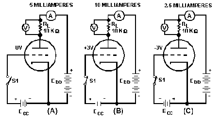
In other words, run the plate current variation (caused by the voltage on the grid) through a resistor, and cause a varying voltage drop across the resistor. This is shown in the next illustration below.

Operation of the plate load resistor.
The circuit is identical to the one in the first illustration above except that now a resistor (called a plate-load resistor, RL) has been added to the plate circuit, and a voltmeter has been added to measure the voltage drop across RL.
In view (A) of the 2nd illustration, the control grid is at 0 volts. Once again 5 milliamperes flow in the plate circuit. Now, the 5 milliamperes must flow through RL. The voltage drop is equal to:
E = I × R
E = (5 × 10⁻³ amperes) × (10 × 103 ohms)
E = (5 × 10-3) × (10 × 10 3)
E = 5 × 10
E = 50 volts
Thus the voltage drop across the plate-load resistor, RL, is 50 volts when no voltage is applied to the grid. In view (B) of the figure, +3 volts is applied to the control grid. Once again plate current increases to 10 milliamperes. The voltage drop across RL is
E = I × R
E = (10 × 10-3 amperes) × (10 × 103 ohms)
E = (10 × 10-3) × (10 × 103)
E = 10 × 10
E = 100 volts
By applying +3 volts to the grid, the voltage drop across RL was increased by 50 volts (from the original 50 volts to 100 volts). In view (C), -3 volts has once again been applied to the control grid. Once again plate current decreases to 2.5 milliamperes, and the voltage drop across RL drops to 25 volts.
We have caused the voltage
across RL to vary by varying the grid voltage; but is it amplification?
Well, let's take a look at it. The grid voltage, or input signal, varies
from +3 to -3 volts, or 6 volts. The voltage drop across RL varies from
25 volts to 100 volts, or 75 volts. In other words, the triode has
causeda 6-volt input signal (varying) to be outputted as a signal that
varies by 75 volts. That's amplification!
An Introduction to Grid Bias
Triode Operation
Overdriven triode and the factors affecting this condition
Tube Bias
Grid leak biasing and shunt grid leak biasing
Operating Classes of Tube Amplifiers
Transit Time, MU Transconductance, and amplification factors.
Transconductance of an electron tube
Interelectrode capacitance
Development of the Tetrode, basic tetrode circuit, tetrode characteristics, and the pentode.


