Coupling Method
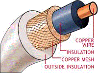
One coupling method used for energy (rf) to be removed from a magnetron is by means of a COUPLING LOOP. At frequencies lower than 10,000 megahertz, the coupling loop is made by bending the inner conductor of a coaxial cable into a loop. The loop is then soldered to the end of the outer conductor so that it projects into the cavity, as shown in view A of the figure below. Locating the loop at the end of the cavity, as shown in view B, causes the magnetron to obtain sufficient pickup at higher frequencies.

View A: Magnetron coupling methods.

View B: Magnetron coupling methods.
The SEGMENT-FED LOOP METHOD is shown in the figure below view C. The loop intercepts the magnetic lines passing between cavities. The STRAP-FED LOOP METHOD (view D), intercepts the energy between the strap and the segment. On the output side, the coaxial line feeds another coaxial line directly or feeds a waveguide through a choke joint. The vacuum seal at the inner conductor helps to support the line. APERTURE, OR SLOT, COUPLING is illustrated in view E. Energy is coupled directly to a waveguide through an iris.

View C: Magnetron coupling methods.

View D: Magnetron coupling methods.

View E: Magnetron coupling methods.
MAGNETRON TUNING
A tunable magnetron permits the system to be operated at a precise frequency anywhere within a band of frequencies, as determined by magnetron characteristics.
The resonant frequency of a magnetron may be changed by varying the inductance or capacitance of the resonant cavities. In the next figure below, an inductive tuning element is inserted into the hole portion of the hole-and-slot cavities. It changes the inductance of the resonant circuits by altering the ratio of surface area to cavity volume in a high-current region.
The type of tuner illustrated in the figure below is called a SPROCKET TUNER or CROWN-OF-THORNS TUNER. All of its tuning elements are attached to a frame which is positioned by a flexible bellows arrangement. The insertion of the tuning elements into each anode hole decreases the inductance of the cavity and therefore increases the resonant fre.quency. One of the limitations of inductive tuning is that it lowers the unloaded Q of the cavities and therefore reduces the efficiency of the tube.

Inductive magnetron tuning.
The insertion of an element (ring) into the cavity slot, as shown in the following figure below, increases the slot capacitance and decreases the resonant frequency. Because the gap is narrowed in width, the breakdown voltage is lowered. Therefore, capacitively tuned magnetrons must be operated with low voltages and at low-power outputs. The type of capacitive tuner illustrated in the figure below is called a COOKIE-CUTTER TUNER.
It consists of a metal ring inserted between the two rings of a double-strapped magnetron, which serves to increase the strap capacitance. Because of the mechanical and voltage breakdown problems associated with the cookie-cutter tuner, it is more suitable for use at longer wavelengths. Both the capacitance and inductance tuners described are symmetrical; that is, each cavity is affected in the same manner, and the pi mode is preserved.

Capacitive magnetron tuning.
A 10-percent frequency range may be obtained with either of the two tuning methods described above. Also, the two tuning methods may be used in combination to cover a larger tuning range than is possible with either one alone.
(back)
(top)
(next)
(return to microwaves page)


